A short introduction to SVG-edit v.2.6-preAlpha
by Luigi D.
CAPRA
SVG-edit is a free SVG pictures editor.
Written in JavaScript, SVG-edit has been designed to be at your side when you need more, that is when you edit web-pages on-line, trying to adapt or recycle available SVG pictures to illustrate a different text.
You don't need to bring SVG-edit with you on CD-ROM or pen-drive because SVG-edit is always accessible through the net. If you need it just enter the following URL in your preferred browser:
http://svg-edit.googlecode.com/svn/tags/stable/editor/svg-editor.html
and open a SVG-edit session. SVG-edit could be spawn by all the major browser: FireFox, Safari, Opera, Crome and of course Internet Explorer 6.
Otherwise, if you prefer, you can integrate SVG-edit capabilities in your HTML page, including a line like this:
<iframe src="http://svg-edit.googlecode.com/svn/tags/stable/editor/svg-editor.html" width="750" height="600"/>
But this is another story.
In this short introduction we will adopt final user point of view regarding SVG-edit like a black box, that means that we will ignore what happen inside. Please note we will make reference to SVG-edit stable release v2.5 and/or SVD-edit v2.6-preAlpha which is embedded in BlueGriffon “Gudea” version 1.1.1.
1 - Screen organization
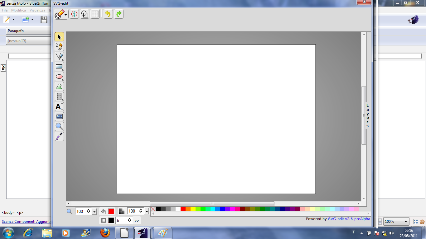
SVG-edit v2.6 preAlpha overlapped to BlueGriffon version 1.1.1
SVG-edit windows consists of two zones: a large central painting area (canvas) and an external frame used as a support for palette of tools and/or colors.
Looking at the frame we may distinguish among the icon toolbar (above), the tools palette (on the left side), the color selection palette (under the canvas) and the layers selection box (hidden on the right side).
Notation
In the following text the notation <CTRL>+X indicates that you may press control-key and “X” key in the same time, <ENTER> that you may press the enter-key and so on.
1.1 - The icon toolbar
One of the most important things you must to know about SVG-edit is that the “icon toolbar” is contest sensitive, that means that the“icon toolbar” looks changes whereas you are working. For instance if you draw a rectangle and then click on it a new set of icons will be show at the right of the basic set adding new controls which allow to move, resize and rotate the selected object.

Icons toolbar basic tools
The “icon toolbar” basic set consist of six icons: the main menu, the edit source, the wireframe mode, show grid, undo and redo icons. Look at the picture above.
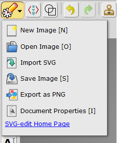
The main menu offers many options (picture above) concerning mainly the creation and the safeguarding of the pictures.
SVG-edit provides short-cuts for the most frequently used commands via control keys. For instance “New Image [N]” means that you can create a new canvas pressing <CTRL>+N.
That theoretically, because your browser could have reserved many control codes for its purposes so not always the short-cut works. You must check control-code combinations on your browser to see what happen; in any case the you can always click on the corresponding icon.
Looking at the icons of the “Main menu” we can see:
1.1.1 - New Image
Clicking on “New Image” icon or pressing <CTRL>+N SVG-edit will ask if you want to discard the current work and create a new, empty, image.
1.1.2 - Open Image
Clicking on “Open Image” icon or pressing <CTRL>+O will open a dialogue box allowing the selection of the selected SVG image for editing.
1.1.3 - Import SVG
Import SVG command allows you to import an existing SVG images in your page.
Please note: the imported image doesn't substitute the previous image which will be preserved.
The image imported will be inserted as a bundle in the left upper corner of the canvas, on the top of the active-layer stack. After insertion you can move or resize the imported image as a whole. If you want to recycle single elements of the imported picture you must before unbind the bundle clicking on the “ungroup icon” (see § 1.3.1).
The ”Import image” option is a very effective way to recycle image elements present in other picture saving time and efforts. If you have to draw many pictures sharing same particular graphic element could be convenient to create a library, that could be saved as a SVG file. When you need components you can import the library and copy the components that you need in the new picture.
1.1.4 - Save Image
Clicking on “Save Image” icon or pressing <CTRL>+S will force the browser to create a new tab showing a new document containing current SVG picture. Then you can save the picture using the save options of the browser.
Please note: sometimes “Save Image” option doesn't work. If this problem occurs you can however save the work done recurring to “Edit Source” following the procedure described at the end of §1.2.
1.1.5 - Export as PNG
Because only few programs support SVG image format SVG-edit allows to export the rendering of the vector graphic image as a bitmap. “Export as PNG” option forces the browser to create a new tab showing the rendering of current SVG picture. Then you can save the corresponding bitmap, as a PNG file, using the save options provided by the browser.
1.2 – Edit Sources
As you know SVG picture consists of a set of commands which tell the graphic engine the sequence of steps to draw the given image.
Clicking on the “Edit Sources” icon or pressing <CTRL>+U switch SVG-edit in text mode allowing the editing of the script corresponding to the SVG picture. This function is very useful for debug purposes allowing expert users to check the correctness of the code generated by the program. “Edit sources” also offers the possibility to manually trim features that are not accessible through the graphics user interface.
When you finish you can decide to save your work pressing “apply changes” (which will force the rendering engine to redraw the picture using the modified script), or discard the changes pressing the “Cancel” button.
If you cannot save the picture draw using the standard SVG-edit's command “Save Image” (see § 1.1.4) you can however safeguard the work done recurring to the following alternative procedure: starting from the graphic environment click on “Edit Sources” icon, then select the whole SVG code pressing <CTRL>+A and copy the text in the clipboard pressing <CTRL>+C. Then create a new text file using an external program (for instance Windows' NotePad), copy the SVG code inside, pressing <CTRL>+V and save the script as a text file. Finally change its extension from “txt” to “svg”.
1.1.6 - Document Properties
Clicking on “Document Properties” icon or pressing <CTRL>+I (<CTRL>+P in BlueGriffon), opens a dialogue box, which offers many possibility to customize SVG-edit behavior; for instance you can change on the fly the size of the canvas, that is the size of the bitmap that should be generated
Because SVG images are stored as sets of vector, changing canvas dimensions doesn't affect the picture contents or image quality. It simply means that the rendering engine must use a different bitmap output-size rendering the picture.
Also “Document Properties” dialogue box allows to give a name to the picture, to select the language used for menu, captions and messages to the user and last by not least offers the possibility to change icons dimensions to adapt to the size of the screen that you are using. This is very useful if you are outside and try to modify a SVG picture using a smart-phone or a PDA.
1.1.7 – Wireframe Model
Clicking on “Wireframe Model” icon or pressing <CTRL>+F makes the layers transparent so that you can see through them checking components alignment. Wireframe option makes also visible lines having stroke width zero that otherwise are invisible allowing to delete them.
1.1.8 - Undo
Clicking on “Undo” icon or pressing <CTRL>+Z recovers the status of the picture immediately precedent last modification.
Please note: SVG-edit supports multiple Undo.
1.1.9 - Redo
Clicking on “Redo” icon or pressing <CTRL>+Y recovers the changes undone using Undo.
1.2 - The layers selection box
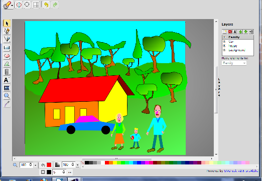
SVG pictures organization is based on layers. You can regard to layers as traditional transparent acetate sheets on which you can draw using felt-tip pens. You can allocate a layer for the background and one or many layers for the characters on the foreground. For instance in the picture below consists of four layer: background, house, car and family.
Layers allows to realize dynamic effect (movement) simply displacing one layer respect the others, without having to redraw your pictures.
Layers employment offers also another benefit because simplify object selection inside the picture.
It is very hard to manage complex vector images consisting of a single layer because the difficulties to select particular object for editing when too many objects or strokes overlap.
Splitting complex graphics among many layers improve objects separation and make easier to select the desired element because only the objects belonging to the active layer could be selected, other details are still visible but not take part to the selection activities.
To open the “Layers selection box” you have to click on it or to drag its left border to the left.
As you can see in the picture above the “Layers dialogue box” shows the list of the layers used to make the SVG image. The active layer is highlighted. Graphic changes affect only the selected layer. You can change the active layer simply clicking on the name of the one that you want to modify. You can also move the selected graphic element to another layer simply selecting the destination layer using the “Move elements to:” entry.
Upon the layer list there are five icons: new layer, delete layer, rename layer, move layer up, move layer down.
1.2.1 – New Layer
“New Layer” creates a new (empty) layer on the top of the layer-stack and select it for editing.
1.2.2 – Delete Layer
“Delete Layer” option deletes the selected layer.
1.2.3 – Rename Layer
New layer receive sequential names: “Layer 1”, “Layer 2”, and so on. “Rename layer” option allows you to change the default name assigning to the currently selected layer a descriptive name.
1.2.4 – Move Layer Up
“Move Layer Up” allows to move a layer in foreground.
“Move Layer Up” and “Move Layer Down” allows you to reorder the layers in function of the distance (of the corresponding object by the point of view) managing occlusions. The layers corresponding to objects in foreground should be on the top of the stack. Layers corresponding to graphic elements partially occluded (behind) by other object should appear under the layer in front of them.
1.2.5 – Move Layer Down
“Move Layer Down” allows to move a layer in background.
1.2.6 – How to transfer a picture element from a layer to another
To move a picture element P from a layer X to a layer Y you must at first select the layer X containing P. Select the elements that you want to move using the selection arrow and finally choose the destination layer using the drop down menu “Move elements to”.
1.3 – Tools palette
On the left side of the canvas you can find the “Tools Palette”. SVG-edit v2.5 palette consists of ten icons: select tool, pencil tool, line tool, rectangle, ellipse, path tool, text tool, image tool, zoom tool, eye dropper tool. BlueGriffon's SVG-edit v2.6_preAlpha offers also the possibility to copy simple clip-arts from a library.
1.3.1 - Selection tool
The arrow tool could be used to select one or more elements of the picture. The selected elements could be simple strokes or complex object defined as a group of simpler components.
You can select a single element of the picture clicking on it, instead if you would like to select a set of elements you must choose the starting point of the selection and the drag the cursor (maintaining the left button pressed) till the end of the selection. When you release the left button all the elements included in the selection rectangle (look at the picture below) will be selected.
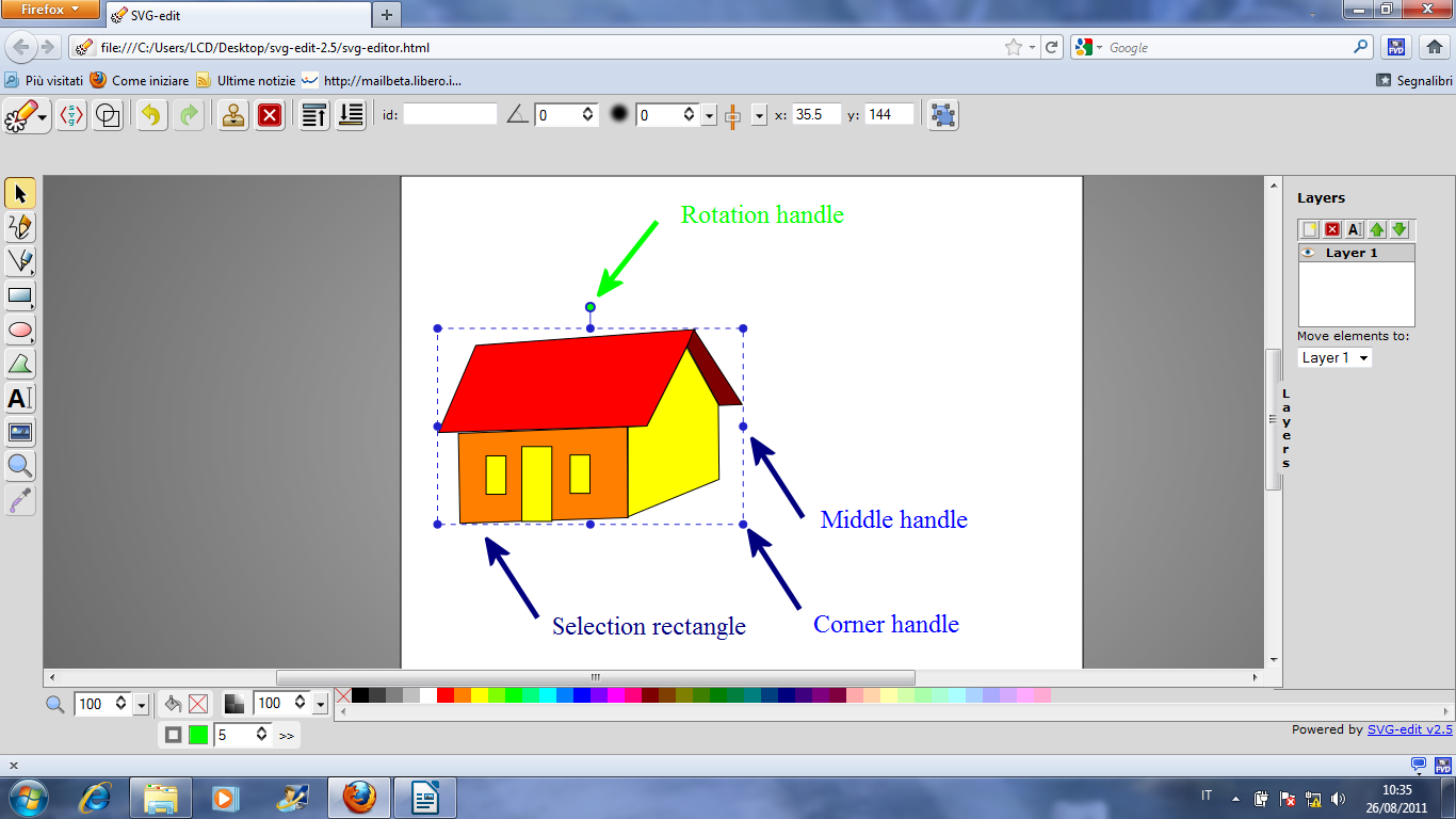
The selection rectangle shows many handles which allows to rotate, resize and deform the selected elements (scrap) in different ways. If you would like change the width of the scrap maintaining the height you should grasp the middle handle on the left (right) side and displace it. The same procedure applied to the upper or lower middle handle allows to change the height of the scrap maintaining the same width. Grasping on of the corner-handles you can resize the scrap, but the most interesting handle is the rotation handle which allows to rotate the scrap.
At the end of the selection a new set of icons will appears in the icons toolbar above the canvas (look at the picture below).

The left most icon (two blue overlapped rectangles) allows to bind together the selected elements creating a compound object (bundle or group). The icons at the right manage selected object alignments allowing to align them respect the position of a reference point.
You can choose the reference point using the drop-down menu “Relative to:” which offers four possibility: selected object, largest object, smallest object, page.
Choose a reference point you can align the selected object horizontally or vertically in six different way: Align Left, Align center, Align right, Align top, Align middle, Align top.
You can group elements pressing the icon showing overlapped rectangles or pressing <CTRL>+G, modifies the appearance of the selection. The elements once independent now appears in the selection like a whole. Selecting more then one elements every individual object appears bound by a dash rectangle after grouping dashed rectangles disappear replaced by a unique solid line rectangle bounding the whole group. Grouping affect also the “Icon toolbar” appearance.

As you can see in the picture above the group and align icons have been replaced by the icons controlling the position of the (new) element in the canvas and and in the local stack (that is the stack of the element belonging to the selected layer).
In the right most position we find again an icon showing two overlapped rectangles. Clicking on the “Ungroup elements” icon or pressing <CTRL>+G you can unbind the bundle.
An effective way to move some objects, belonging to the same layer, maintaining the relative positions is to make a bundle, move it to destination as a whole and the unbind.
Bundled elements behave as a whole, that means that you can move, rotate, resize, change color to the grouped elements with a single command. When you have finish you can unbind them. They return to behave as separated independent elements.
The “Selection tool” could also be used to pick-up the color of an elementary graphic element. After the selection the filling-color and the border-color of the selected element will become the actual colors.
1.3.2 - Pencil tool
The “pencil tool” allows free hand drawing. The thickness and the color of the strokes could be changed using the “Color Palette” tools. See § 1.4.
1.3.3 - Line tool
The “Line tool” could be used to draw a straight lines from a point A to a point B.
1.3.4 - Rectangle/Square/Free hands rectangle
Clicking on the “Rectangle” icon opens a sub-menu palette offering the choice among three different options: Rectangle, Square and Free hands rectangle drawing. The first two options are very straightforward. The third option allows the user to sketch a free hand rectangle that will be converted in a true rectangle immediately after the completion. This option could be very useful if you are using a PDA.
1.3.5 - Ellipse/Circle/Free hands ellipse
Clicking on the “Ellipse” icon opens a sub-menu palette offering the choice among three different options: Ellipse, Circle and Free hands ellipse drawing. The first two options again are very straightforward. The third option allows the user to sketch a free hand ellipse that will be converted in a true ellipse immediately after the completion. This option could be very useful if you use certain kind of PDA.
1.3.6 - Path tool
The “Path tool” allow polylines and polygons drawing. Polylines could be regarded as open polygons, that is polygons incomplete because a side is missing.
To draw a polygon consisting of three vertex A, B, C, you must click on point A, B, C, and then on A again. To draw a polyline consisting of three vertex A, B, C, you must click on point A, B, C, and then on C again.
Note that: if the path include at least three vertex, the inside of the polyline could be filled exactly as the inside of a polygon. SVG-edit behave like if the polyline was close on itself by a side connecting the first and the last vertex. In this case the only different between a polygon and a polyline having the same vertex is that, if a stroke width greater then zero is selected the strokes corresponding to sides of the polyline will be marked but not the missing side.
1.3.7 - Text tool
SVG's format supports also text writing. To introduce a text in the drawing you must use the “text tool” (the “A” shaped icon”). To enter a text click on the “A” icon, then move the cursor in the place where you want to write, click on the left mouse button and type the desired text.
Please note: there is a little bug because at first the text will be paint using invisible ink. Don't worry go on. When you finish to write click on the color palette the text will appear immediately.
Analogously if you change font family or font size the color will be reset. You should click again on the color palette to make the text visible.
1.3.8 - Image tool
SVG format allows bitmap integration in vector graphic picture. To embed a bitmap in your SVG picture click on the monitor shaped icon to select the “Image tool” then move the cursor in the place where you want to insert the image and click again. A dialogue box will appear asking: “Enter the new image URL”. If the image that you want to embed is accessible through the Web type the corresponding URL, otherwise if it is present in computer type: “file:///” followed by the corresponding path.
For instance supposing you are working under Windows-7 and you would like to embed the file MyImage.jpg on your desktop you should type something like this:
file:///C:/Users/<your_name>/Desktop/MyImage.jpg
1.3.9 - Zoom tool
SVG-edit provides two different zoom tools the lens icon (in the “Tools Palette”) and the “Change zoom level” (see § 1.4.1). The lens tools it is very easy to use, just select the details that you want to see better and automatically SVG-edit will show them as large as possible.
1.3.10 - Eye dropper tool
In SVG-edit the“Eye dropper tool” works like the color can in others paintings programs, that is you can use the “Eye dropper tool” to change both the filling color and the stroke color of an object using the active colors.
1.3.11 - Clip-art library
SVG-edit v2.6_preAlpha offers also the possibility to insert in the picture standard symbols and shapes copying them from a library of clip-arts. The library provided with BlueGriffon consists of twelve sets of symbols: basic, object, symbols, arrows, flowchart, animals, cards and chess, dialog balloons, electronics, mathematical, music and miscellaneous.
1.4 – Colors palette
You can find the “Colors palette” on the bottom of the window just under the canvas.
Really the left most control doesn't concern colors selection but all other do.
1.4.1 – Change zoom level
The left most control (drop down menu) allows the user to choose the preferred zoom level. The main difference between “Change zoom level” and the “Zoom tool” (see § 1.3.9) is that “change zoom level” allows the user to select the preferred zoom factor whereas the “Zoom tool” enlarge the selected details as wide as possible.
1.4.2 – Change fill color
Immediately at the right of “Change zoom level” you can find “Change fill color”, where the filling color is the color that will be used to fill the inside of polygon and polylines.
Clicking on the bucket icon open a dialogue box which allows to set the filling color choosing it ina a palette or specifying RGB or HSB coordinates.
SVG-edit supports three different painting strategies or styles: solid color, linear gradient or radial gradient. Selecting solid color the whole inside of the polygon will be paint using the selected filling color. The linear gradient option paints the selected object using different shades of color changing linearly moving on the selected line. Finally, the radial gradient option allows to paint the selected object using different shades of colors moving from the center toward the borders.
1.4.3 – Change the selected object opacity
The “checkers” icons allows you to change the opacity of the selected object in reference to the background. A completely transparent object has an opacity of 0% whereas an opaque object as an opacity of 100%. Partially transparent objects could have intermediate opacity level.
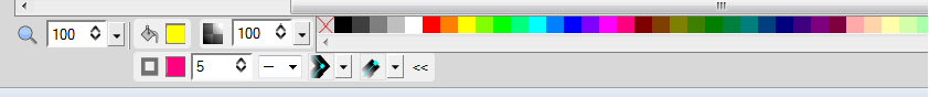
1.4.4 – Traditional palette of colors
At the right of the opacity selection control you can find a traditional palette of colors. To change the filling color simply click on the color cell that shows the desired color. To change the stroke color you must click on the color cell that shows the desired color pressing <SHIFT> in the same time.
1.4.5 – Change stroke color
Immediately under the bucket icon there is a square icon; pressing on it you can change the stroke color. The color selection dialogue box has been already described in § 1.4.2, look there for more information.
1.4.6 – Change stroke width
The drop menu immediately at the right of “Change stroke color” allows to change the line width. A polygon with a stoke width of zero will appears without borders.
1.4.7 – Change stroke dash style
This allows to change polylines dash styles.
1.4.8 – Change corners style
This options allows you to choose among sharp corners or rounded ones.
1.4.9 – Change strokes butts
In computer graphics straight lines (having thickness greater then one) often looks like thin rectangles. Change stroke butts drop down menu lets you choose among round and squared butts.
1.5 – Selected object modifiers

As we have already observed the “Icons toolbar” is context sensitive that means that it tries to offer always the set of icons more suitable for the current editing conditions; in particular after object selection the “Icons toolbar” shows on the right many auxiliary icons which permits to manipulate the selected object in many different ways.
From left to right you can see: Clone element, Delete element, Move to top, Move to bottom, Convert to path, Identify the element, Change rotation angle, Change gaussian blur value, Align element to page, Change X coordinates, Change Y coordinates, and many other option depending from the kind of object selected.
1.5.1 – Clone element
Clicking on the timbre icon will create a copy (that is another instance) of the selected object.
1.5.2 – Delete elements
Clicking on Delete elements or simply pressing <DEL> button will delete the selected objects.
1.5.3 – Move to Top
“Move to Top” command will force the reordering of the object stack (corresponding to the selected layer) forcing the selected object to move toward the foreground. This command doesn't affect unselected layers stack.
1.5.4 – Move to Bottom
“Move to Bottom” command will force the reordering of the object stack (corresponding to the selected layer) forcing the selected object to move toward the background. This command doesn't affect unselected layers stack.
1.5.5 – Convert to path
“Convert to path” options convert rectangles in an oriented path.
1.5.6 – Identify the element
SVG-edit users are encouraged to create their own library of graphic components, as a way to simplify complex design reusing standard “bricks”.
“Identify the element” shows always the name of the object currently selected. Changing the selection force an immediate“Identify the element” status update.
“Identify the element” offers also an easy way to change default object names. You must simply edit the name of the object replacing the old name with the new one.
1.5.7 - Change rotation angle
When you insert a new object in the canvas, for instance a rectangle or an ellipse, it is oriented in standard way that is parallel to the X and Y axes. SVG-edit provides two different way to change the selected object orientation: you may grasp and simply turn the rotation handle until the object assumes the desired orientation (see § 1.3.1) or you can set the rotation required using “Change rotation angle” dial. The first procedure it is more intuitive the latter more precise.
1.5.8 - Change gaussian blur value
SVG allows element blurring to simulate fading due to fog or smoke presence or also the distortion due to occlusion by partially transparent object.
1.5.9 - Align element to page
Clicking on “Align element to page” open a dialogue box which allow to align the selected object to the page in the selected way. Object may be aligned to: the left, the center, the right, the top, the middle, the bottom.
1.5.10 - Change X coordinates
“Change X coordinate” move the left side of the selection rectangle in the position specified.
1.5.11 - Change Y coordinates
“Change Y coordinate” move the upper side of the selection rectangle in the position specified.
1.6 – Path modifiers
Selecting an oriented path the “Icons toolbar” changes showing the following options: link control points, change X node coordinate, change Y node coordinate, change segment type, clone node, delete node, open close sub-path, add sub-path. Look at the picture below.

Talking about path object we may distinguish between two different kind of selection: standard selection and node selection. Standard selection is the same selection mechanism that works with all the other kind of object, which force the selected object to appear bounded by a selection rectangle (see § 1.3.1). Clicking again on a path object the selection rectangle disappears replaced by a new representation, which enhance nodes position showing little circles in vertex correspondence. Node selection also enhance a segment of the path using a particular color (cyan) which become the selected segment. “Path modifiers” allows the user to modify the path in different way: moving the node or replacing the segment with a bezier-curve which could be deformed freely.
You can also change the selected node (and segment) clicking on a different node.
Please note: to distinguish between standard selection and node selection you could look at the cursor shape. In the first case the cursor is an arrow in the second is a four arrow cross.
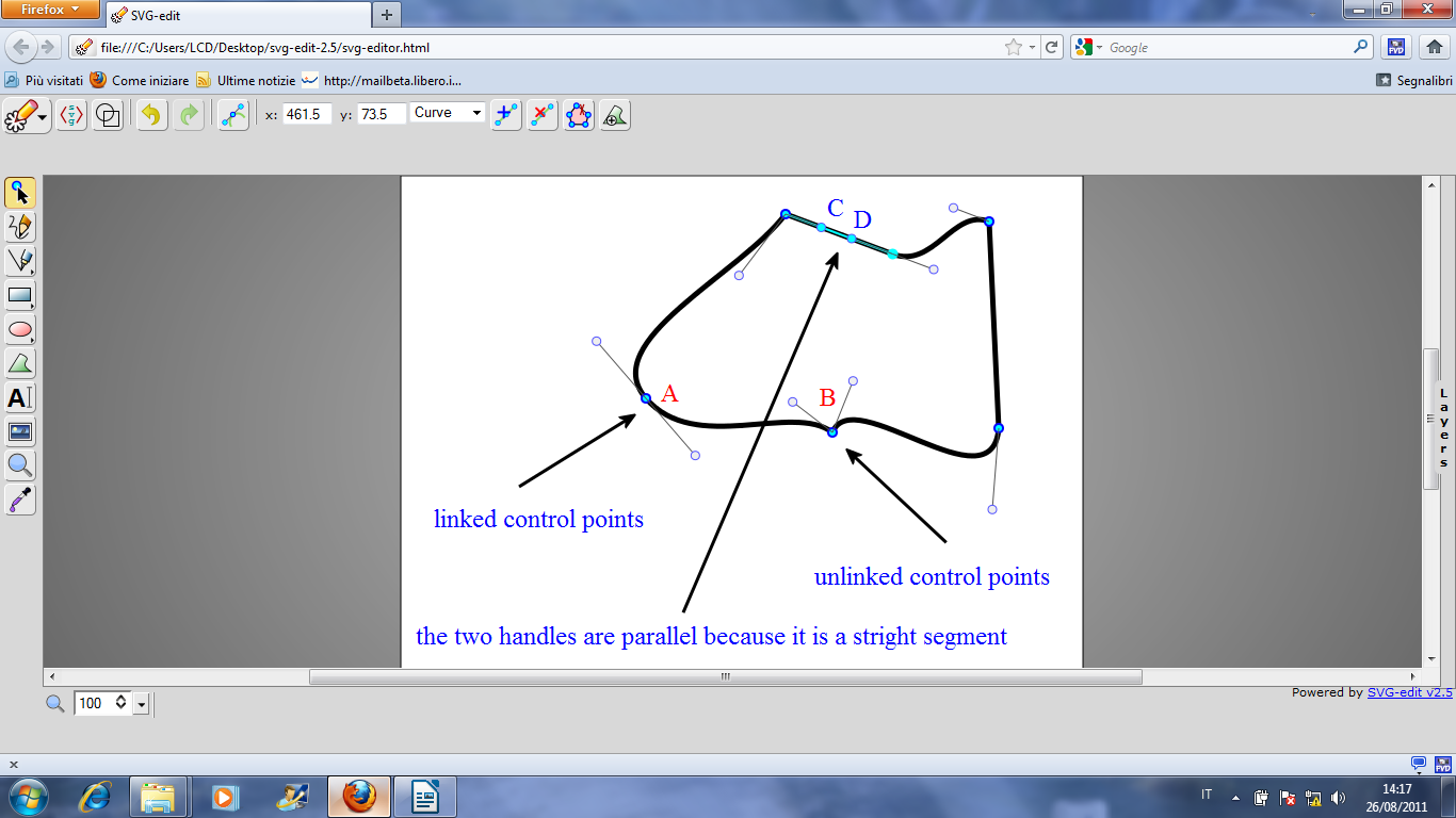
1.6.1 - Link control points
“Link control points” toggles between linked and unlinked control point modes.
Assuming that some segments of the current path were already be replaced by curves, supposing that exist as least one node that joins two different curves (look at the previous picture). Typically the tangents of the two curves entering and exiting from the given point will be different (as in point B) but in particular situations could be necessary to assure that the two curve has the same tangent in a node, this result could be get linking the control points (look at the point A).
The “Link control points” icon toggles between linked and unlinked control point modes. Usually we work in unlinked control points mode, allowing the two tangent to be different, but if it is necessary it is possible to toggle to linked control point mode clicking on the corresponding icon. When linked control points mode is active selecting a handle will immediately force the handle corresponding to the other curve to align (as in point A). Then grasping one of the two linked handles you can modify ad the same time the looks of the two linked curves.
To go back to the unlinked mode click again on the “Link control points” icon.
1.6.2 - Change X node coordinate
“Change X node coordinate” dial allows fine tuning of the selected node position (the node marked with a solid cyan circle).
1.6.3 - Change Y node coordinate
“Change Y node coordinate” dial allows fine tuning of the selected node position (the node marked with a solid cyan circle).
1.6.4 – Change segment type
“Change segment type” control allows to choose between two options: straight and curve.
At the creation path objects looks like sequence of segments but the user is free to replace one or more of the segment joining couple of node vertex with curves. It is also possible to revert a curve to a segment.
To replace a segment with a curve: select the segment that you want to transform in a curve selecting one of its node (if the segment selected is not the right one click on the other node), then simply open “Change segment type” drop down menu and select curve. Do the converse if you want revert a curve in a segment. Immediately after the transformation two handles will appear. The two small cyan circle on the segment. Grasp one of the handle and move it to modify the shape of the curve.
Please note: the direction and of the handles have a straightforward geometrical interpretation, by convention the direction of the handle is the same of the line tangent to the curve in the given node. The length of the handle which is proportional to the coefficient of the Beziér equations could be regarded as the intensity of the strength that should be used to deform a spline to get the given deformation.
1.6.5 – Clone node
Clicking on the “Clone node” icon will force the insertion of a new control node in the middle of the selected segment.
1.6.6 – Delete node
Clicking on the “Delete node” icon will delete the selected control node.
1.6.7 – Open close sub-path
Paths usually were created as closed circuits (similar to polygons border) but in some situations the user could need an open path. Clicking on “Open close sub-path” you can delete the selected segment or restore it if it has been deleted.
1.6.8 – Add sub-path
The “Add sub-path” option allows you to create a sub-path connected with the existing one.
1.7 – Lines decoration

Selecting a segment (stroke) the “Icons toolbar” shows on the right three special icons which allows segment decoration adding markers.
The three icons behave in the same way allowing to select the start marker type (s:), select the mid marker type (m:) or select the end marker type (e:). Clicking on one of the three icons will appear a palette of markers which allows to choose the markers that you would like to use to decorate you stroke. You must employ at most three markers one for the start, one for the middle and one for the end of the stroke.
1.7.1 – Drawing an arrow
For instance supposing you would like to draw an arrow you must at first draw a segment using the “Line tool”. Draw a segment directed toward the top of the canvas, select the segment using the “Selection tool”. Then click on the right most icon (e:) and select the arrow head directed toward the right.
If you would like to add feather on the queue, click on (s:) icon and select the marker that you prefer.
2 – Conclusions and future work
SVG-edit seem to be a good program, providing powerful tools that allows to edit vector graphics images also when you are not in office. When I will have time I will write another chapter writing providing some examples of the use of SVG-edit.
For now, thanks to Narendra Sisodiya, Pavol Rusnak and all the people of the SVG-edit team.